Arduino - Push button LED circuit | Full Code & Circuit Diagrams
In this tutorial, we'll learn how to control an LED using a push button with an Arduino. We'll go through the circuit diagram, the components required, and two versions of Arduino code. The first version is a basic implementation, while the second is more optimized. By the end of this tutorial, you'll understand how to set up the circuit and write the code to control an LED using a push button.
Components Required
- Arduino Uno R3
- Pushbutton
- 220 Ω Resistor
- Red LED
- 680 Ω Resistor
- Breadboard and jumper wires
Circuit Diagram
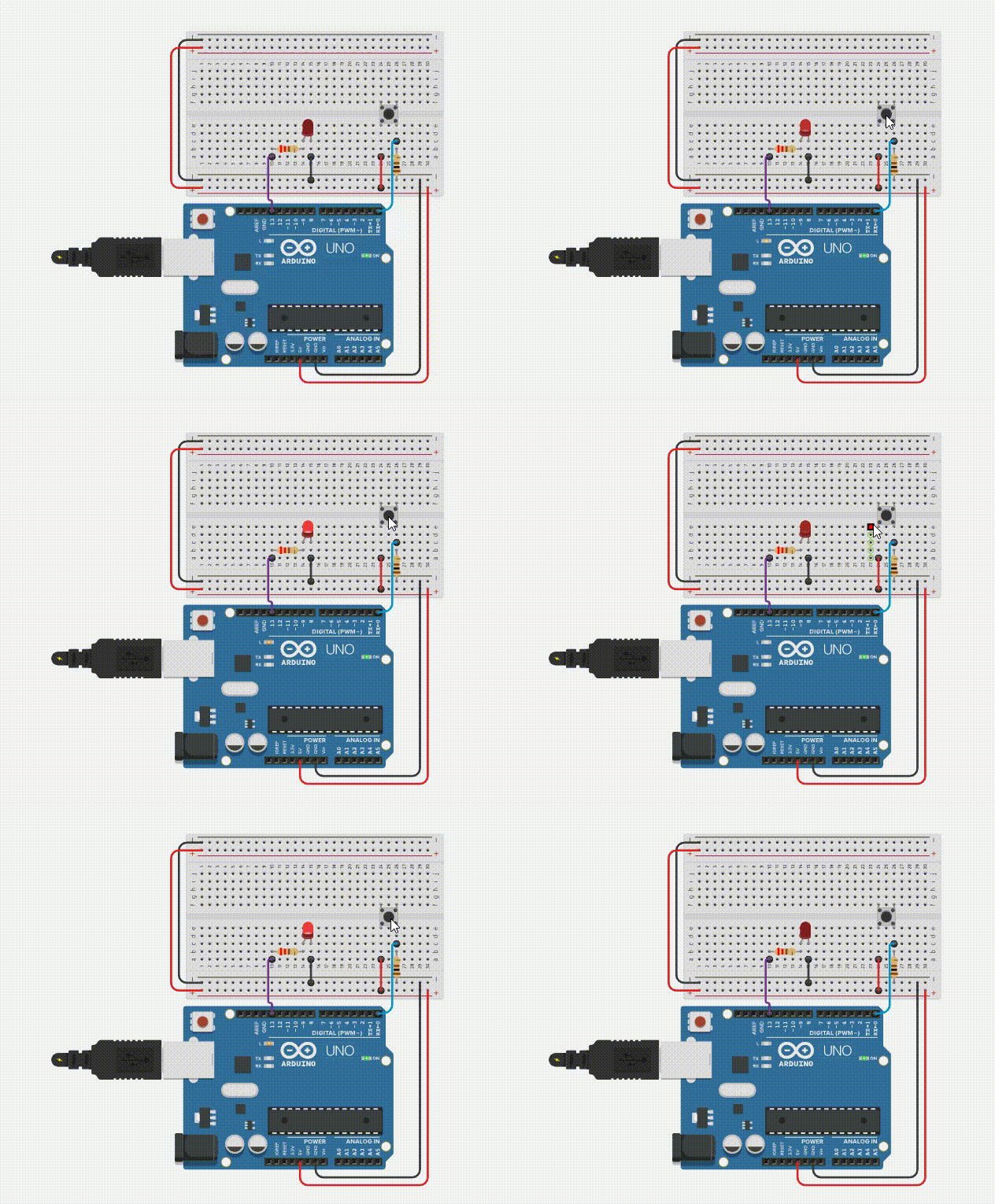
Below is the circuit diagram showing the connections for our project:


Circuit Description
- The push button is connected to pin D0 of the Arduino.
- The built-in LED (connected to pin D13) is used for this project.
- The 680 Ω resistor (R1) is connected to the push button as an Pull-down resistor.
- The 220 Ω resistor (R2) is connected in series with the LED to protect it from excessive current.
Arduino Code
We'll provide two versions of the code. The first one is a basic implementation, and the second one is a more optimized version.
Basic Implementation:
// Arduino Code for Switching ON/OFF an LED with a Push Button

#define led LED_BUILTIN // Using Arduino's Built-in LED, also Pin D13
#define pb 0 // Push Button on Pin D0 of Arduino

bool state; // Boolean Variable to store button state

void setup() {
  pinMode(led, OUTPUT); // Set LED pin as Output
  pinMode(pb, INPUT); // Set Push Button pin as Input
}

void loop() {
  state = digitalRead(pb); // Store Button State in "state" Variable
  digitalWrite(led, state); // Turn ON LED if state is true or turn OFF LED if state is false
}
Basic Implementation
In the basic implementation, we use a boolean variable state to store the state of the push button. The digitalRead() function reads the state of the push button and stores it in the state variable. The digitalWrite() function then sets the state of the LED based on the value of the state variable. This approach works perfectly, but it involves an extra variable which can be optimized.
Optimized Implementation
In the optimized implementation, we directly use the digitalRead() function inside the digitalWrite() function. This eliminates the need for an extra variable, making the code more efficient and concise. The functionality remains the same, but the code is shorter and easier to read.
Code 2: Optimized Implementation
// Arduino Code for Switching ON/OFF an LED with a Push Button

#define led LED_BUILTIN // Using Arduino's Built-in LED, also Pin D13
#define pb 0 // Push Button on Pin D0 of Arduino

void setup() {
  pinMode(led, OUTPUT); // Set LED pin as Output
  pinMode(pb, INPUT); // Set Push Button pin as Input
}

void loop() {
  digitalWrite(led, digitalRead(pb)); // Read Push Button and Update LED
}
Conclusion
In this tutorial, we learned how to control an LED using a push button with an Arduino. We went through the circuit diagram and the components required. We also provided two versions of the Arduino code - a basic implementation and a more optimized version. By following this tutorial, you should be able to set up the circuit and write the code to control an LED using a push button.